- Why Is It Important to Understand RLAF Construction Before Selecting Equipment?
- What Is RLAF and How Is Its Construction Different from Standard LAF?
- What Are the Main Components of an RLAF?
- Equipment Body and Construction Materials of RLAF
- What Is the Role of the Working Zone in RLAF?
- Fan System in RLAF: The Component That Drives Airflow
- What Filtration Stages Does the RLAF Filtration System Include?
- The Role of the HEPA Filter in RLAF Construction
- Return-Air System and Air Path in RLAF
- Differential Pressure Gauge, Sensors, and Monitoring System in RLAF
- Lighting, Control Panel, and Supporting Operation Components
- How Do RLAF Components Work Together During Operation?
- Common Construction-Related Mistakes in RLAF
- Criteria for Evaluating RLAF Construction in Cleanroom Projects
- Testing and Maintenance of Main RLAF Components
- FAQ – Frequently Asked Questions About RLAF Construction
- Conclusion: RLAF Construction Determines Dust-Control Performance at the Working Zone
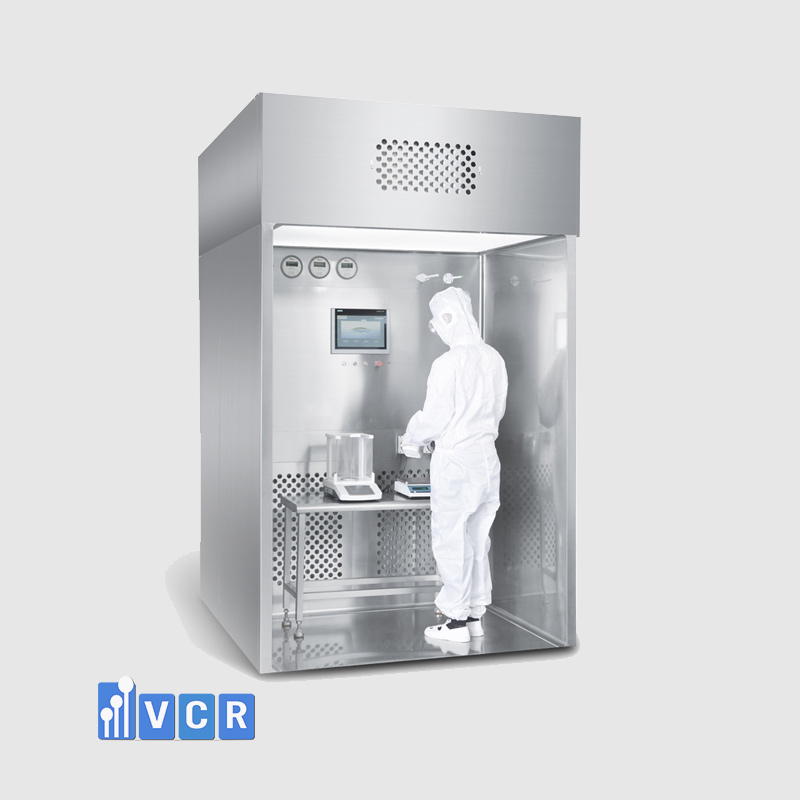
RLAF is a reverse laminar airflow device used in cleanrooms to control dust, particles, and contaminants generated at the working zone. In pharmaceutical factories, cosmetic factories, nutraceutical facilities, chemical plants, laboratories, or controlled manufacturing areas, RLAF is commonly used at points with dust dispersion risks, such as raw material weighing areas, sampling areas, active ingredient handling areas, or powder material handling zones. For the equipment to operate effectively, it is not enough to only check whether the RLAF has a HEPA Filter. It is necessary to understand the entire structure of the device.
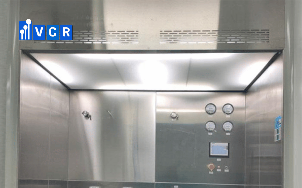
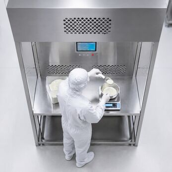
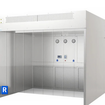
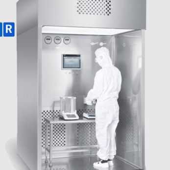
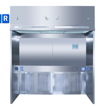
A complete RLAF is the coordination of the equipment body, working zone, fan system, filtration system, HEPA Filter, return-air path, differential pressure gauge, control panel, lighting, and supporting components for operation. In this system, the HEPA Filter captures fine particles, the fan generates airflow, the working zone is where dust-related risks arise, and the return-air system collects dust-laden air and directs it toward the filters. Only when these components are designed as a coordinated system can RLAF control dust at the working zone and support stable cleanroom operation.
Why Is It Important to Understand RLAF Construction Before Selecting Equipment?
In actual cleanroom equipment selection, many people first ask whether the RLAF uses HEPA H13 or H14, whether it has a HEPA filter, or what airflow volume it provides. These specifications are important, but they are not enough to evaluate the entire device. RLAF is not simply a filter installed in a stainless steel frame, nor is it only a fan that creates airflow. RLAF is a localized airflow-control system in which every component must work together correctly to collect dust, filter air, and maintain a stable working zone.
If attention is given only to the HEPA Filter while the working zone is ignored, the device may use a good filter but operators may still place raw material bags, containers, or tools in a way that blocks the return-air path. If only a powerful fan is considered without calculating the correct air velocity, airflow may blow powder more strongly and create turbulence inside the working chamber. If equipment is selected only by external dimensions without analyzing actual operations, the working zone may be too small or too large for the process, reducing dust-control effectiveness.
Understanding RLAF construction helps factories and contractors view the device as a complete system. The equipment body provides structure and working space. The working zone is where dust is generated. The fan drives the airflow. The return-air system draws dust-laden air toward the filters. The pre-filter, medium filter, and HEPA Filter handle different particle levels. The differential pressure gauge monitors filter condition. The control panel supports operation and monitoring. Lighting supports accurate handling. Each component has its own role, but no component should be evaluated entirely in isolation.
In cleanroom projects, misunderstanding RLAF construction may cause many issues after installation. A factory may select the wrong working-zone size, the wrong filter grade, a fan with insufficient pressure, a design with inadequate filter replacement space, a device that is difficult to clean after operation, or equipment that cannot meet qualification requirements. For cleanroom contractors, evaluating RLAF construction from the design stage helps position the equipment correctly according to layout, cleanliness class, personnel flow, material flow, and actual operating requirements.
Therefore, before asking how much an RLAF costs or which filter grade it uses, it is necessary to understand what components the equipment includes and how each component affects dust-control performance. This is the foundation for selecting RLAF for the right purpose, operating it stably, and maintaining it proactively throughout the equipment lifecycle.
What Is RLAF and How Is Its Construction Different from Standard LAF?
RLAF stands for Reverse Laminar Air Flow, meaning a reverse laminar airflow device. In this term, “reverse” means opposite or reversed, while “Laminar Air Flow” means laminar airflow. RLAF is used to control dust, particles, or contaminants generated at the working zone by directing and collecting dust-laden air into the filtration system. This equipment is commonly used in areas such as powder raw material weighing, raw material sampling, active ingredient handling, chemical preparation, or handling easily dispersed materials.
LAF stands for Laminar Air Flow, meaning a laminar airflow device. A standard LAF is usually designed to supply clean air through a HEPA Filter into the working zone to protect products, samples, or tools from environmental dust. With LAF, the main objective is often product protection. Clean airflow passes through the working zone and helps limit environmental airborne particles from contacting the product.
RLAF has a different objective. It does not only create clean air, but also focuses on collecting dust generated from the working zone itself. When operators handle powder or active ingredients, the dust source does not come from the external environment but from the material being handled. If clean air is supplied in the same way as a standard LAF, dust may be pushed out of the working zone or toward the operator. RLAF is therefore designed to control dispersion, helping dust-laden air move toward the return-air or suction area.
This difference directly affects equipment construction. LAF usually focuses on the clean-air supply area, HEPA filter surface, and airflow direction for product protection. RLAF must focus simultaneously on the working zone, return-air position, air path, dust-collection ability, fan capacity, filter grade, and airflow stability. If the return-air system in an RLAF is poorly designed, the equipment cannot collect dust effectively even when it uses a good HEPA Filter.
In short, LAF focuses on creating a clean-air zone, while RLAF focuses on controlling dust generated at the working zone. Therefore, when reviewing RLAF construction, it is necessary to consider not only the filter but also the entire air path: where air enters, where dust is generated, where dust-laden air is drawn, how filtration works, and how the operator works inside the controlled zone.
What Are the Main Components of an RLAF?
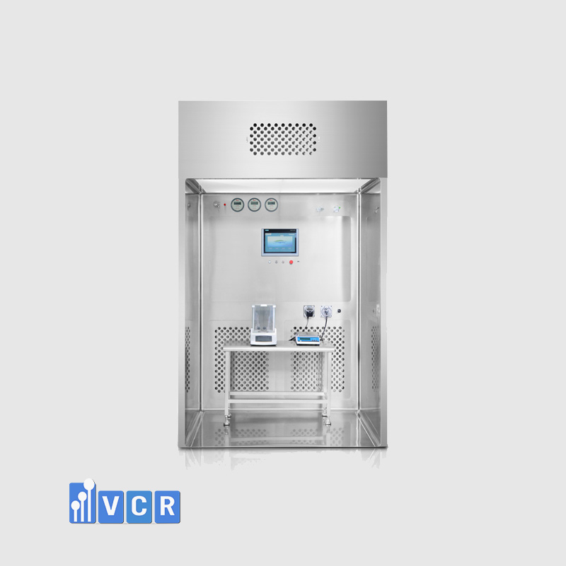
An RLAF device typically includes multiple components that work together to create a localized dust-control system in a cleanroom. Depending on the manufacturer, size, application, and project requirements, the detailed construction may vary. However, an RLAF generally includes the equipment body, frame, working zone, fan system, filtration system, HEPA Filter, return-air path, return-air surface, differential pressure gauge, control panel, lighting, doors or screens if present, leveling feet or wheels, filter testing ports, and maintenance-support components.
The equipment body is the main frame of the RLAF. It provides structure, defines the working chamber, and protects internal components such as the fan, filters, air paths, and electrical system. In cleanrooms, the equipment body is usually made from stainless steel or a material suitable for hygiene, durability, and cleanability requirements. Surfaces should be smooth, have minimal gaps, and be easy to clean to reduce dust accumulation risks.
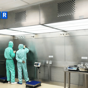
The working zone is where operators perform tasks such as weighing materials, sampling, dispensing powder, handling chemicals, or working with active ingredients. This is the most important area from an operational perspective because dust is usually generated directly here. The working-zone size, height, depth, tabletop, scale position, container placement, and tool arrangement all directly affect dust-control performance.
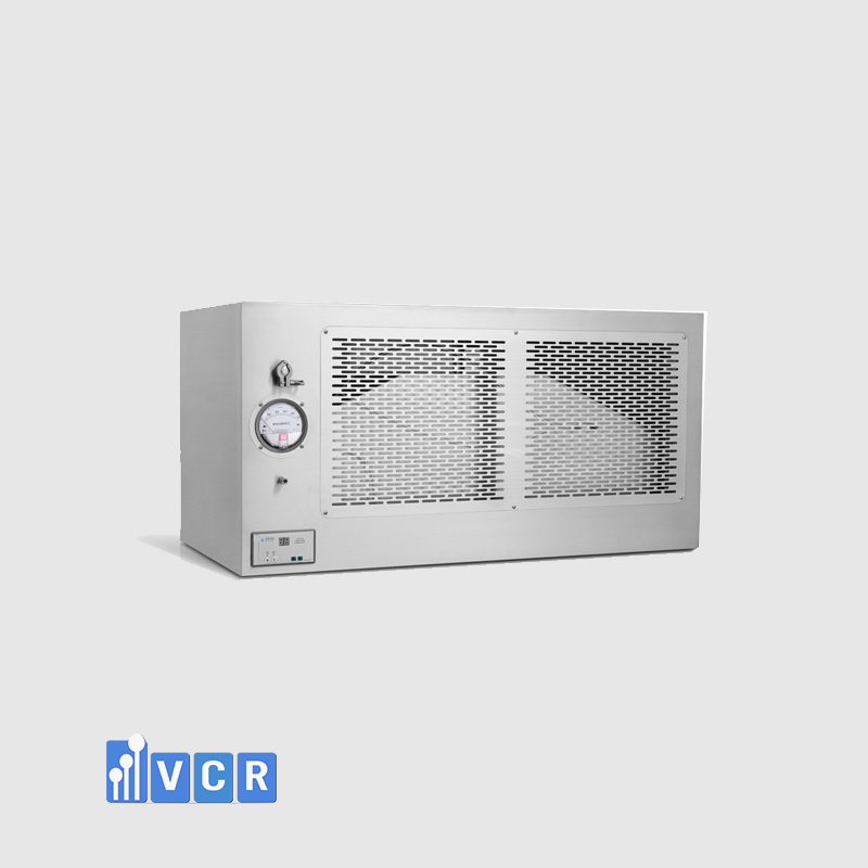
The fan system generates the driving force for airflow. The fan helps supply air, extract air, return air, or recirculate air depending on the design. If the fan does not have enough capacity or is not suitable for the resistance of the filtration system, the required airflow volume may not be achieved. If the fan is too strong or improperly adjusted, airflow may create turbulence and cause more dust dispersion.
The filtration system usually includes a pre-filter, a medium filter if required, and a HEPA Filter. A pre-filter is a primary or coarse filter used to capture large dust particles. A medium filter is an intermediate filter that helps reduce the load on the final filter. A HEPA Filter stands for High Efficiency Particulate Air, meaning a high-efficiency air filter that captures fine particles in the airflow. The filtration system is important, but it only performs effectively when air passes properly through the filters and the filter frame is tightly sealed.
The return-air system includes return-air grilles, return-air surfaces, return-air chambers, or return-air paths. Return air means air drawn back into the system. This component collects dust-laden air from the working zone and directs it into the filtration system. It is a very important part of RLAF because the equipment does not only supply clean air; it must also collect generated dust.
In addition, the differential pressure gauge monitors filter condition, the control panel supports equipment operation, lighting assists handling, and components such as doors, screens, wheels, leveling feet, and testing ports improve usability, stability, and maintainability. Overall, RLAF should be viewed as an integrated system, not as a set of separate parts.
Equipment Body and Construction Materials of RLAF
The equipment body is the foundation of RLAF. It provides mechanical structure, defines the working chamber, protects the filtration and fan system, and directly affects cleanability in the cleanroom. If the equipment body is not rigid enough, not sufficiently sealed, or has many gaps, airflow may leak, dust may accumulate, and cleaning after operation will become more difficult.
In cleanrooms, RLAF construction materials are usually required to have smooth surfaces, low dust retention, easy cleanability, and compatibility with the production environment. Stainless steel is commonly used in cleanroom equipment because it is durable, relatively corrosion-resistant, easy to clean, and suitable for areas requiring dust, microbial, or light chemical control depending on the application.
Depending on project requirements, RLAF may use stainless steel for the entire equipment body or only for parts directly exposed to the working zone. High-requirement areas such as pharmaceutical, cosmetic, or nutraceutical production often prioritize smooth stainless steel surfaces, fewer joints, fewer sharp edges, and fewer hard-to-clean points. In areas handling color powders, active ingredients, or chemicals, equipment surfaces must be especially easy to wipe down to avoid residue after each operation.
The tightness of the equipment body is also important. RLAF must control the path of air. If the body has unwanted gaps, air may leak out or move through the wrong path. This reduces dust-collection performance and may affect pressure conditions inside the equipment. Tightness is not only related to the frame but also to doors, screens, gaskets, filter installation points, and connection areas.
The equipment-body design should also consider rounded corners and cleanability. Deep square corners, narrow gaps, hard-to-reach joints, or rough surfaces may become dust-accumulation points. In cleanrooms, residual dust does not only create hygiene issues but also increases cross-contamination risk. Therefore, a good RLAF body must be both mechanically stable and supportive of fast, clear, and controllable cleaning procedures.
For cleanroom contractors, when evaluating an RLAF body, it is necessary to review material, surface finish, compatibility with the layout, maintenance clearance, electrical connection position, leveling capability, and operating stability. A device with a good filtration system but a hard-to-clean or poorly sealed body may still create difficulties in real operation.
What Is the Role of the Working Zone in RLAF?
The working zone is the area where operators directly perform tasks inside the RLAF. This is where activities such as material weighing, sampling, powder dispensing, bag opening, material pouring, chemical handling, or active ingredient handling take place. It is also the area where dust, particles, or contaminants are likely to be generated directly. Therefore, the working zone is not simply an empty workspace. It is an airflow-controlled zone that plays a decisive role in RLAF performance.
The working zone must be large enough for operators to place scales, containers, trays, raw material bags, and tools without blocking critical airflow paths. If the zone is too small, operators may easily place items in front of the return-air area or disturb the airflow. If the zone is too large but the fan and airflow volume are not designed accordingly, dust may not be drawn effectively into the return-air system.
The depth and height of the working zone are also very important. If the depth is insufficient, operators may need to work near the front edge of the equipment, increasing the risk of dust escaping from the controlled area. If the height is unsuitable, opening bags, pouring powder, or handling containers may become inconvenient. When operators must lean forward, move their hands outside the controlled zone, or position materials incorrectly, RLAF effectiveness decreases.
Airflow pattern means the way airflow is distributed and moves. In the working zone, the airflow pattern must remain stable so that generated dust is drawn toward the return-air area. If there are too many obstacles, airflow may become disturbed. Turbulence means disturbed airflow that no longer moves in a stable direction. A dead zone is an area with weak airflow or poor air exchange. Both turbulence and dead zones may cause dust to remain suspended longer or escape outward.
The working zone also affects operator safety and comfort. A properly sized RLAF helps operators work naturally, reduces poor posture, reduces random placement of tools, and makes cleaning after use easier. Conversely, if the working zone is inconvenient, operators may unintentionally violate procedures, such as blocking return air, moving materials outside the controlled zone, or allowing dust to settle on hard-to-clean surfaces.
When selecting RLAF, actual operation should be simulated from the beginning. Are materials brought in by bags, drums, or trays? Where will the scale be placed? Where will the operator stand? In which direction will powder be poured? Where should tools be placed? How will cleaning be done after operation? These questions help determine the correct working-zone size and airflow structure. If equipment is selected only based on standard dimensions, it may not suit the real process.
Therefore, the working zone is one of the most important parts of RLAF. It is where risks arise, where operators interact with the equipment, and where airflow must be controlled most precisely.
Fan System in RLAF: The Component That Drives Airflow
The fan system in RLAF provides the driving force for the entire airflow-control process. A fan generates airflow, while a blower may refer to a centrifugal or air-moving fan depending on the design context. In RLAF, the fan does not simply make the device “have air.” It determines airflow volume, the ability to overcome filter resistance, airflow stability, and operating noise level.
Airflow volume means the amount of air processed per unit of time. Air velocity means the speed of airflow at a specific point. Static pressure indicates the fan’s ability to overcome system resistance such as filters, air paths, return-air grilles, and equipment chambers. Noise level refers to operating sound. All of these parameters are directly related to the fan.
If the fan is too weak, RLAF cannot create enough airflow to draw dust from the working zone into the return-air system. Dust may then remain suspended in the working chamber or escape into the cleanroom. If the fan does not have enough static pressure to overcome the resistance of the HEPA Filter and other filtration stages, actual airflow volume may be lower than designed. This is why the fan cannot be selected only by electrical power or size. It must be suitable for the entire filtration system and air path.
Conversely, if the fan is too strong or not adjusted properly, airflow may create turbulence in the working zone. With lightweight powder materials, excessive air velocity may cause stronger powder dispersion and more dust release instead of better control. Therefore, in RLAF, stronger airflow does not automatically mean higher effectiveness. What matters is that airflow must move in the correct direction, at the correct speed, and in a way that matches the handled material.
The fan also affects noise level and operator comfort. An RLAF that operates too loudly may cause discomfort, especially in areas used regularly. High noise may also indicate that the fan is not operating optimally, that vibration is occurring, or that there is a problem in the air path. Therefore, noise level should be evaluated together with airflow volume and air velocity when selecting RLAF.
In some designs, the fan may include speed control to adjust operation according to filter condition or operating requirements. As filters gradually become loaded, resistance increases and the system must maintain suitable airflow volume. However, fan adjustment must be controlled based on technical specifications and test results, not by feeling.
The fan system is the aerodynamic heart of RLAF. But this heart only works effectively when it is properly connected with the working zone, return-air system, and filters. A good fan selected with the wrong airflow volume, wrong pressure, or placed in a poor air-path design can still reduce dust-control performance.
What Filtration Stages Does the RLAF Filtration System Include?
The filtration system is an important part of RLAF construction. Its function is to capture dust, particles, and contaminants in the airflow. Depending on the design and project requirements, RLAF may use several filtration stages, commonly including a pre-filter, medium filter, and HEPA Filter. Each filtration stage has its own role and helps the system operate stably while protecting the final filter from becoming overloaded too quickly.
A pre-filter is a primary or coarse filter. This filter usually captures large dust particles, fibers, and coarse impurities in the airflow. In areas where powder is handled, large dust particles may be generated during bag opening, material pouring, or equipment cleaning. Without a pre-filter, this dust load may go directly into later filtration stages, causing the HEPA Filter to become dirty quickly and differential pressure to rise rapidly.
A medium filter is an intermediate filter. This filter captures smaller particles after air has passed through the pre-filter. Not every RLAF includes a medium filter, but in many configurations, intermediate filtration improves system stability and reduces the load on the HEPA Filter. For applications with high dust generation, a multi-stage filtration configuration is often beneficial because it extends stable operating time before the final filter requires replacement.
HEPA Filter stands for High Efficiency Particulate Air, meaning a high-efficiency air filter. This is the key filtration stage for capturing fine particles in the airflow. In cleanrooms, HEPA Filters are commonly used to ensure that filtered air meets appropriate particle-control requirements. The HEPA Filter may be located at the supply-air position, return-air path, or air-treatment system depending on the RLAF design.
A multi-stage filtration system helps RLAF operate more stably. The pre-filter and medium filter protect the HEPA Filter. If these earlier filters are not cleaned or replaced correctly, the HEPA Filter can become dust-loaded quickly. When the HEPA Filter becomes dirty, differential pressure rises, airflow volume decreases, and dust-control performance may be affected. Therefore, filtration maintenance is not only about replacing the HEPA Filter; the upstream filtration stages must also be considered.
The filtration system must be selected based on dust-generation level, handled material type, and qualification requirements. A powder raw material weighing area may generate more dust than a small sample-handling area in a laboratory. Color powders, active ingredients, and chemicals also have different filtration and cleaning requirements. A single filtration configuration should not be applied automatically to every RLAF application.
The filtration system is where particles are handled in the airflow, but it is only effective when air passes properly through the filters. If the filter frame is not sealed, the gasket is inadequate, or the air path leaks, air may bypass the filter. Therefore, filtration construction must be combined with tightness, testing capability, and differential pressure monitoring.
The Role of the HEPA Filter in RLAF Construction
The HEPA Filter is one of the most discussed components in RLAF construction. HEPA stands for High Efficiency Particulate Air, meaning a high-efficiency air filter. Its main role is to capture fine particles in the airflow, helping filtered air achieve the particle-control level required for the cleanroom.
In RLAF, the HEPA Filter may appear in different positions depending on equipment configuration. Some designs place the HEPA Filter at the supply-air area to create clean airflow into the working zone. Some designs use the HEPA Filter in the return-air path or in the system that treats dust-laden air. Other configurations combine multiple filtration stages to both supply clean air and treat return air. The important point is that the HEPA Filter position must match the airflow-control objective of the equipment.
HEPA H13 and HEPA H14 are high-efficiency filter grades commonly used in environments that require strict particle control. H14 usually has higher filtration efficiency than H13, but this does not mean every RLAF must use H14. Filter grade selection should be based on target cleanliness class, handled material type, dust-generation level, qualification requirements, and overall equipment design. If a high-grade filter is selected but the fan cannot handle its resistance, airflow volume may not meet the design requirement.
A very important point is that the HEPA Filter alone does not determine the entire performance of RLAF. A device may use a good HEPA Filter, but if the filter frame is not sealed, air may leak around it. A gasket is the sealing component that ensures air passes through the filter media instead of bypassing through gaps. If the gasket is inadequate, the filter frame is improperly installed, or the filter has leakage, filter integrity will be affected.
HEPA leak testing checks for leakage in the HEPA Filter installation. This is an important test used to confirm that the filter and its installation area have no leak points. In cleanroom projects with strict qualification requirements, HEPA leak testing helps ensure that air does not bypass the filter. Without this test, small leak points that affect particle-control performance may go undetected.
The HEPA Filter must also be monitored through differential pressure. Differential pressure refers to the pressure difference across the filter. As the HEPA Filter becomes dust-loaded, resistance increases and differential pressure usually rises. If differential pressure exceeds the allowable range, airflow volume may decrease and the equipment may no longer operate according to design. Conversely, if differential pressure is abnormally low, air leakage or poor filter installation may need to be checked.
The service life of a HEPA Filter depends on dust-generation level, the performance of upstream filters, operating time, cleaning procedures, and working conditions. In powder weighing areas or applications handling dusty materials, the HEPA Filter may be loaded faster than in light laboratory applications. Therefore, filter replacement should not be based only on feeling. It should be based on differential pressure monitoring, test results, and actual operating condition.
The HEPA Filter is important, but it should not be viewed as the only factor. In RLAF, the HEPA Filter performs fully only when the fan generates suitable airflow, the working zone is not blocked, return air functions correctly, and the device is tested periodically. This is the correct way to understand the role of the HEPA Filter in a complete RLAF system.
Return-Air System and Air Path in RLAF
The return-air system is one of the major differences between RLAF and many devices that mainly focus on clean-air supply. Return air means air drawn back into the system. In RLAF, the return-air system collects air carrying dust, particles, or contaminants generated in the working zone and then directs this airflow to the filtration system. Without a proper return-air path, dust may not be collected effectively even if the equipment has a fan and filters.
The return-air system may include return-air grilles, return-air surfaces, return-air chambers, or air ducts depending on the design. A return-air grille is the point where air enters the return path. A return-air surface may be arranged to draw air from the working zone. A return-air chamber is an internal equipment space that guides air toward the filtration system. Each design may differ, but the common objective is to direct dust-laden air into the correct treatment path.
In the working zone, dust is usually generated when operators open bags, pour powder, take samples, or divide materials. RLAF airflow must draw dust toward the return-air area instead of allowing it to move toward the operator or escape outward. Therefore, the return-air position must be designed based on the dust-generation point and actual operation direction. If the return-air area is positioned poorly, dust may move along another path and may not be collected effectively.
A common issue is the return-air area being blocked by raw material bags, trays, containers, or tools. When operators place obstacles in front of the return-air grille, airflow cannot move in the intended direction. Dust may create vortices, remain suspended inside the chamber, or escape outward. This is a common operating mistake, but it can be reduced if the working zone is designed properly and operators are trained correctly.
If the return-air path is poorly designed, it may create dead zones or turbulence. A dead zone is an area where air exchange is weak. Turbulence refers to disturbed airflow that no longer moves in a stable direction. Both phenomena reduce dust-control performance. In RLAF, airflow needs to be stable enough to collect dust but not so strong that it disperses material more.
Smoke testing uses smoke to observe airflow direction. This is a useful method for evaluating the RLAF return-air system. During a smoke test, inspectors can see whether smoke is drawn toward the return-air area, whether dead zones or vortices exist, and whether airflow is being pushed outside the controlled zone. For RLAF, smoke testing is not merely a visual demonstration; it helps confirm whether the air-collection principle is functioning correctly.
The return-air system is essential for RLAF dispersion control. If the HEPA Filter is the place where particles are captured, the return-air system is the part that brings particles to that treatment point. A good filtration system cannot perform well if dust-laden air is not collected through the correct path. Therefore, when evaluating RLAF construction, the return-air position, air path, and risk of obstruction during actual operation must be reviewed carefully.
Differential Pressure Gauge, Sensors, and Monitoring System in RLAF
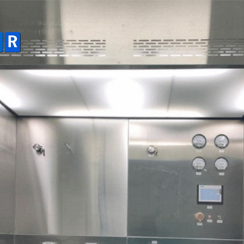
The differential pressure gauge and monitoring system help operators track the operating condition of RLAF during use. A differential pressure gauge displays differential pressure. Differential pressure is the pressure difference before and after a filter. In a filtration system, this parameter helps assess filter condition and supports proactive maintenance.
As the filter gradually accumulates dust, resistance across the filter increases and differential pressure usually rises. If differential pressure exceeds the recommended range, the filter may be dirty or clogged, reducing airflow volume and affecting dust-control performance. If differential pressure is abnormally low, air leakage, loose filter installation, or air bypass may need to be investigated. Therefore, the differential pressure gauge is not merely an indicator. It is a tool for monitoring the health of the filtration system.
In addition to differential pressure, some RLAF units may be equipped with sensors or monitoring functions for other parameters, such as fan status, air velocity, operating time, fault alarms, light status, filter alarms, and operating modes. Depending on the automation level, the control panel may display basic information or include more advanced alarm functions.
Monitoring data helps factories operate equipment more proactively. If operators rely only on the feeling that the equipment is still running normally, they may not realize that airflow volume has decreased, the filter is dirty, or there is an issue in the air path. In cleanrooms, many deviations cannot be detected visually. A running fan does not necessarily mean the equipment still achieves proper control performance.
The differential pressure gauge also supports maintenance planning. Instead of replacing filters only according to a fixed time schedule or waiting until a clear failure occurs, factories can monitor differential pressure trends to determine when filters should be checked, cleaned, or replaced. This reduces operational risks and helps avoid unnecessary production interruptions.
For GMP cleanroom projects, operating-parameter records are also important. GMP stands for Good Manufacturing Practice. Recording differential pressure, test results, maintenance schedules, and filter replacement history helps demonstrate that the equipment is controlled, rather than used based on subjective judgment.
Lighting, Control Panel, and Supporting Operation Components
In addition to main components such as the fan, filters, working zone, and return-air system, RLAF also includes several operation-supporting components. These parts may not directly filter dust, but they affect handling, safety, cleaning, and equipment stability in daily use.
Lighting is an important component in the working zone. Illumination means lighting level. When operators weigh materials, take samples, divide powder, or handle chemicals, sufficient and uniform lighting helps them clearly see materials, tools, scale marks, labels, and surface conditions. If lighting is too weak, operations may become less accurate. If lighting is poorly arranged, shadows may appear and make observation inside the working chamber difficult.
The control panel is where operators switch the equipment on or off, control operating modes, and monitor basic status. A good control panel should be easy to understand, easy to operate, clearly displayed, and designed to minimize mistakes. In some RLAF units, the control panel may integrate differential pressure alarms, fan status, operating time, or system fault alerts.
Doors or screens, if present, also affect airflow. These components may help limit the working zone, reduce the impact of the surrounding environment, or support safety. However, if they are not designed properly, doors or screens may obstruct operation or disturb airflow. Therefore, these components should be evaluated together with the airflow pattern, not only based on mechanical convenience.
Wheels or leveling feet help the equipment remain stable at the installation location. If the RLAF needs to be moved, the wheels must be lockable. If the device is fixed in place, leveling feet help balance it on the floor. Mechanical stability affects vibration, noise, and operational safety.
Maintenance-support components such as filter testing ports, fan access doors, filter replacement access, gaskets, locks, and cleanable surfaces are also very important. A device that is difficult to access for filter checking or internal cleaning will create problems during periodic maintenance. When maintenance is difficult, operators may delay inspection, increasing operational risk.
Therefore, when evaluating RLAF, supporting components should not be treated as unimportant accessories. They directly affect operating experience and the ability to maintain long-term control.
How Do RLAF Components Work Together During Operation?
RLAF operates effectively when all equipment components work together in a unified control chain. The fan generates airflow. The working zone is where dust is generated. The return-air system collects dust-laden air. The filtration stages handle particles. The HEPA Filter captures fine particles. The differential pressure gauge monitors filter condition. The control panel supports operation and alarms. The equipment body keeps the whole structure stable.
When the equipment starts operating, the fan creates the pressure and airflow volume needed to form airflow inside the working chamber. This airflow must pass through the working zone in the designed direction. When operators handle powders, chemicals, or active ingredients, dust generated in the working zone is drawn by airflow toward the return-air system. If the working zone is unobstructed and the return-air area is not blocked, dust follows the controlled path instead of dispersing freely.
Dust-laden air then passes through the filtration system. The pre-filter captures large dust particles, the medium filter if present captures smaller particles, and the HEPA Filter captures fine particles. After filtration, air may be recirculated or further treated depending on the design. Throughout this process, the differential pressure gauge monitors filter condition. If differential pressure rises abnormally, operators can recognize that the filter is becoming dust-loaded and requires inspection.
If one component in this chain does not function correctly, the entire RLAF performance decreases. A fan with incorrect airflow volume creates insufficient or excessive airflow. A poorly installed HEPA Filter allows air to bypass the filter. Incorrect working-zone arrangement blocks return air. Poor return-air positioning prevents dust collection. Failure to monitor differential pressure allows dirty filters to go unnoticed. A hard-to-clean equipment body causes dust residue after operation.
This shows that RLAF is not equipment that works correctly simply because the fan is turned on. It must be operated according to its intended principle. Operators need to know which areas must not be blocked, where materials should be placed, where operations should occur, when cleaning is required, when differential pressure must be checked, and when technical support should be notified.
For contractors, understanding how components coordinate helps evaluate equipment from a system perspective. A catalogue may list HEPA Filter, fan, stainless steel, and lighting, but the key questions are how these components are arranged, how air moves, and whether the device matches the real operation. Only when the components work together correctly can RLAF control dust at the working zone and support stable cleanroom operation.
Common Construction-Related Mistakes in RLAF
A common mistake when selecting RLAF is choosing an unsuitable working-zone size. If the working zone is too small, operators do not have enough space for scales, raw material bags, containers, and tools. They may have to work outside the controlled zone or place obstacles in front of the return-air area. If the working zone is too large but airflow volume is not designed accordingly, dust may not be collected effectively.
The second mistake is focusing only on the HEPA Filter while ignoring the fan and return-air system. The HEPA Filter is very important, but it can only treat air that actually passes through it. If the fan does not provide enough airflow or the return-air system cannot draw dust into the filtration system, the HEPA Filter cannot fully perform its role. A device using HEPA H14 may still control dust poorly if its airflow design is incorrect.
The third mistake is selecting a fan with insufficient pressure. The filtration system, air path, and return-air chamber all create resistance. If the fan does not have enough static pressure to overcome this resistance, actual airflow volume decreases. Conversely, a fan that is too strong but poorly adjusted may create turbulence in the working zone. Therefore, the fan must be selected based on the entire system, not only by power rating.
The fourth mistake is installing the HEPA Filter without proper sealing. If the gasket is poor, the filter frame is not sealed, or the filter is installed incorrectly, air may bypass the filter. This problem is difficult to detect visually without leak testing. Therefore, filter integrity and HEPA leak testing are important during qualification and after filter replacement.
The fifth mistake is not having or not monitoring a differential pressure gauge. If differential pressure is not controlled, the factory will have difficulty knowing when the filter is dirty, when filter replacement is required, or when abnormal signs appear. Checking only when airflow becomes weak or when a visible failure occurs is often too late.
The sixth mistake is designing a return-air area that is easily blocked during real operation. A design may look reasonable on drawings, but if operators frequently place containers or raw material bags in front of the return-air grille, actual performance will decrease. This is why equipment should be evaluated based on real operating procedures, not only technical dimensions.
Other mistakes include a hard-to-clean equipment body, insufficient filter replacement space, inadequate lighting, a difficult-to-use control panel, or equipment unsuitable for the handled material. These issues may lead to inconvenient operation, incomplete cleaning, difficult maintenance, and qualification challenges. When evaluating RLAF, contractors should view the equipment as a complete system rather than focusing only on a few prominent components.
Criteria for Evaluating RLAF Construction in Cleanroom Projects
When selecting RLAF for a cleanroom project, the first criterion is the size and design of the working zone. The working zone must match the actual process, including material type, packaging size, scale position, containers, trays, tools, and operator working space. If the working zone is unsuitable, the equipment will be difficult to operate correctly even if other specifications are good.
The next criterion is material and surface finish of the equipment body. Cleanroom-grade stainless steel is often preferred because it is easy to clean, durable, and suitable for controlled environments. Surfaces should be smooth, with limited gaps, fewer dead corners, and easy-to-clean construction. In areas handling color powders, active ingredients, or chemicals, cleanability is especially important because residual dust may cause cross-contamination.
HEPA filter grade and filtration configuration must also be reviewed carefully. Does the equipment have a pre-filter? Does it have a medium filter? Is the HEPA Filter H13 or H14? Can HEPA leak testing be performed? Is the filter easy to access for replacement? Is the filter sealed with a suitable gasket? These questions help evaluate the actual filtration system rather than only checking the filter grade name.
The fan and aerodynamic parameters are another important criterion. Airflow volume, air velocity, static pressure, noise level, and the ability to maintain stable airflow as filters begin to load should all be reviewed. The fan must match the equipment size, air path, and filter resistance. It should not be selected simply based on the feeling that airflow is strong.
The return-air system should be evaluated based on position, size, risk of obstruction, and dust-collection effectiveness. If the return-air design does not match actual operation, the equipment may fail to control dust at the source. Smoke testing can be used to observe airflow direction during qualification or after installation.
Other criteria include differential pressure gauge, monitoring capability, illumination, control panel, noise level, maintenance space, filter replacement capability, technical documentation, and qualification requirements. A suitable RLAF does not only meet technical specifications; it must also be easy to operate, easy to clean, and easy to test.
As a cleanroom equipment supplier for cleanroom contractors, VCR Cleanroom Equipment can support the selection of RLAF configurations suitable for each project’s layout, handled material, cleanliness class, airflow, and qualification standards. Evaluating construction from the design stage helps reduce the risk of selecting the wrong equipment, lacking operating space, or facing qualification difficulties after installation.
Testing and Maintenance of Main RLAF Components
Testing and maintaining RLAF is not only about replacing filters periodically. Proper maintenance means maintaining stable coordination among airflow, fan, filters, working zone, return-air system, and monitoring system. If one component deteriorates without being detected, the dust-control effectiveness of the entire device may decrease even though the equipment is still running.
The first items to check are air velocity and airflow volume. Air velocity means airflow speed, while airflow volume means the amount of air processed per unit of time. These parameters indicate whether the equipment is creating enough airflow to collect dust. If air velocity is too low, dust may not be drawn into the return-air area. If it is too high, lightweight materials may be disturbed. Testing should be performed at appropriate positions in the working zone, not by subjective feeling at one point.
The next item is filter differential pressure. Differential pressure helps monitor filter condition. When filters become dirty, differential pressure usually rises. If differential pressure is not monitored, the factory may not realize that airflow volume is gradually decreasing. Differential pressure also helps detect abnormal signs such as poor filter sealing or air-path problems.
HEPA leak testing checks for leakage in the HEPA Filter. This test is especially important after HEPA Filter replacement or during equipment qualification. Particle testing measures airborne particles and helps evaluate particle levels in the working zone or related area. Smoke testing uses smoke to observe airflow direction and is very useful for confirming whether the return-air system draws air in the correct direction.
Cleaning the working zone should be performed regularly, especially after handling color powders, active ingredients, chemicals, or adhesive raw materials. Internal surfaces, gaps, corners, tabletops, return-air areas, and dust-accumulation points must be carefully cleaned. If the working zone is not cleaned properly, residual dust may become a cross-contamination source for the next operation.
The fan, lighting, control panel, gaskets, doors, screens, and equipment body also require inspection. The fan should run stably without unusual vibration or noise. Lighting must be sufficient. The control panel must display correctly. Gaskets and sealing areas should remain in good condition. The equipment body should not have damage, gaps, or hard-to-clean dust accumulation points.
Maintenance frequency depends on material type, dust-generation level, operating time, and GMP requirements. An RLAF used daily in a powder weighing area should be inspected more frequently than equipment used occasionally in a laboratory. The important point is that factories need records to document test results, filter replacement, cleaning, and operating abnormalities.
FAQ – Frequently Asked Questions About RLAF Construction
Question: What components does an RLAF include?
An RLAF usually includes an equipment body, working zone, fan system, pre-filter, medium filter if required, HEPA Filter, return-air system, differential pressure gauge, control panel, lighting, doors or screens, leveling feet, wheels, and maintenance-support components.
Question: What is the most important component of an RLAF?
RLAF should not be viewed as having only one most important component. The HEPA Filter, fan, working zone, and return-air system all play core roles. The HEPA Filter captures fine particles, the fan generates airflow, the working zone is where dust is generated, and the return-air system collects dust-laden air into the filtration system.
Question: What is the role of the HEPA Filter in RLAF?
The HEPA Filter is a high-efficiency air filter used to capture fine particles in the airflow. In RLAF, it helps filtered air meet the required particle-control level. However, the HEPA Filter is only effective when installed tightly, without leakage, and when airflow passes correctly through it.
Question: Does RLAF need a pre-filter?
In many applications, RLAF should have a pre-filter to capture large dust particles, fibers, and coarse impurities before air reaches later filtration stages. The pre-filter helps reduce the load on the HEPA Filter and supports more stable filtration-system operation.
Question: What does the fan do in RLAF?
The fan drives airflow and helps supply air, extract air, return air, or recirculate air depending on the design. It affects airflow volume, air velocity, static pressure, and noise level. If the fan is unsuitable, RLAF may not control dust effectively.
Question: How does the working zone affect dust-control performance?
The working zone is where operators work and where dust is generated. If the zone is too small, too large, poorly arranged, or blocks return air, airflow may become disturbed and dust may not be collected properly. Therefore, the working zone must match the actual process.
Question: What is the purpose of the differential pressure gauge in RLAF?
The differential pressure gauge monitors filter condition. When filters become dirty, differential pressure usually rises. If differential pressure is abnormal, filters, filter frames, gaskets, or the air path may need to be checked. It is an important tool for proactive maintenance.
Question: How important is the return-air system in RLAF?
The return-air system collects dust-laden air from the working zone and directs it into the filtration system. If return air is blocked or poorly designed, dust may not be collected effectively. It is one of the most important elements in RLAF construction.
Question: When should the HEPA Filter in RLAF be replaced?
The HEPA Filter should be replaced when differential pressure exceeds the limit, test results fail, the filter is damaged, leakage is detected, or according to the factory’s maintenance plan. Filter replacement should be based on operating data, not only on subjective judgment.
Question: What should contractors consider when evaluating RLAF construction?
Contractors should evaluate working-zone size, equipment-body material, filtration system, fan, return-air system, differential pressure monitoring, HEPA leak testing capability, maintenance space, cleanability, and suitability for layout, handled material, and qualification requirements.
Conclusion: RLAF Construction Determines Dust-Control Performance at the Working Zone
RLAF is not only a HEPA Filter. It is a system made up of multiple coordinated components. The equipment body provides structure and supports cleaning. The working zone is where dust-related risks arise. The fan drives airflow. The return-air system collects dust-laden air and directs it toward the filters. The pre-filter, medium filter, and HEPA Filter handle different particle levels. The differential pressure gauge and control panel help monitor operating status.
In this system, the HEPA Filter captures fine particles, the fan determines airflow volume and air velocity, and the working zone determines whether the device matches the actual process. If any of these elements is unsuitable, RLAF dust-control performance may decrease even though the equipment still appears to operate normally.
When contractors and factories correctly understand RLAF construction, they can select more suitable equipment, position it more effectively, operate it more stably, and maintain it more proactively. This is the foundation for reducing cross-contamination risks, supporting operator protection, and improving the likelihood of meeting qualification requirements in GMP cleanroom projects.
Hai VCR